
ESP32-C6-DevKitC-1-N8 Development Board (8 MB SPI Flash)
We have ✅ 1 available of the DF-DFR1054 in our Sydney warehouse. An extra 114 units will be available shortly.
ESP32-C6-DevKitC-1 is an entry-level development board based on ESP32-C6-WROOM-1, a general-purpose module with an 8 MB SPI flash. This board integrates complete Wi-Fi, Bluetooth LE, Zigbee, and Thread functions. Most of the I/O pins are broken out to the pin headers on both sides for easy interfacing, so developers can either connect peripherals with jumper wires or mount ESP32-C6-DevKitC-1 on a breadboard as per their needs. The board can be used in applications such as smart home, industrial automation, health care, consumer electronics, service robots, and IoT data loggers.
ESP32-C6-DevKitC-1 is built around ESP32-C6, a RISC-V 32-bit single-core CPU that operates at up to 160 MHz, and integrates a rich set of peripherals. Users can power off the CPU and make use of the low-power co-processor to constantly monitor the peripherals for changes.
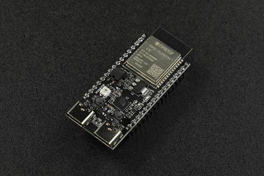
Figure: Components
| Key Component | Description
| ESP32-C6-WROOM-1 | ESP32-C6-WROOM-1 is general-purpose module supporting Wi-Fi 6, Bluetooth 5, and IEEE 802.15.4 (Zigbee 3.0 and Thread). It's built around the ESP32-C6 chip, and comes with an 8 MB SPI flash. ESP32-C6-WROOM-1 uses on-board PCB antenna. For more information, see ESP32-C6-WROOM-1 Datasheet.
| Pin Header | All available GPIO pins (except for the SPI bus for flash) are broken out to the pin headers on the board.
| 5 V to 3.3 V LDO | Power regulator that converts a 5V supply into a 3.3V output.
| 3.3 V Power on LED | Turns on when the USB power is connected to the board.
| USB-to-UART Bridge | Single-chip USB-to-UART bridge provides transfer rates up to 3 Mbps.
| ESP32-C6 USB Type-C Port | The USB Type-C port on the ESP32-C6 chip is compliant with USB 2.0 full speed. It is capable of up to 12 Mbps transfer speed (Note that this port does not support the 480 Mbps high-speed transfer mode).
| Boot Button | Download button. Holding down Boot and then pressing Reset initiates Firmware Download mode for downloading firmware through the serial port.
| Reset Button | Press this button to reset the system.
| USB Type-C to UART Port | Used for power supply to the board and the communication with the ESP32-C6 chip via the on-board USB-to-UART bridge.
| RGB LED | Addressable RGB LED, driven by GPIO8.
| J5 | Used for current measurement. See details in Section Current Measurement.
Figure: Block Diagram
Pin Header: The two tables below provide the Name and Function of the pin headers on both sides of the board (J1 and J3). The pin header names are shown in the figure of ESP32-C6-DevKitC-1 Layout.
Figure: J1 Pin Layout
Figure: J3 Pin Layout
Figure: Pin Layout
The differences between ESP32-C6-DevKitM-1 and ESP32-C6-DevKitC-1-N8
The ESP32-C6-DevKitM-1 is based on the ESP32-C6-MINI-1 (U) module, which has a 4 MB SPI flash, while the ESP32-C6-DevKitC-1-N8 is equipped with the ESP32-C6-WROOM-1 module, which has an 8 MB flash.
The amount of flash memory can affect the amount of data that can be stored on the board and the complexity of the programs that can be run on it.
Applications
Smart home
Industrial automation
Health care
Consumer electronics
Service robots
IoT data loggers
Specification
Processor: ESP32-C6 chip, RISC-V 32-bit single-core
ROM: 320 KB
SRAM: 512 KB HP SRAM
16 KB LP SRAM
16 KB LP SRAM
Integrated 40 MHz crystal oscillator
8 MB SPI flash
Support Thread 1.3
Support Zigbee 3.0
Operating voltage/Supply voltage: 3.0-3.6 V
Recommended operating temperature range: –40 to 85°C
Documents
Shipping List
ESP32-C6-DevKitC-1-N8 Development Board × 1
The ESP32-C6-DevKitC-1-N8 Development Board (8 MB SPI Flash) appears in the following collections:
SKU DF-DFR1054
by Little Bird